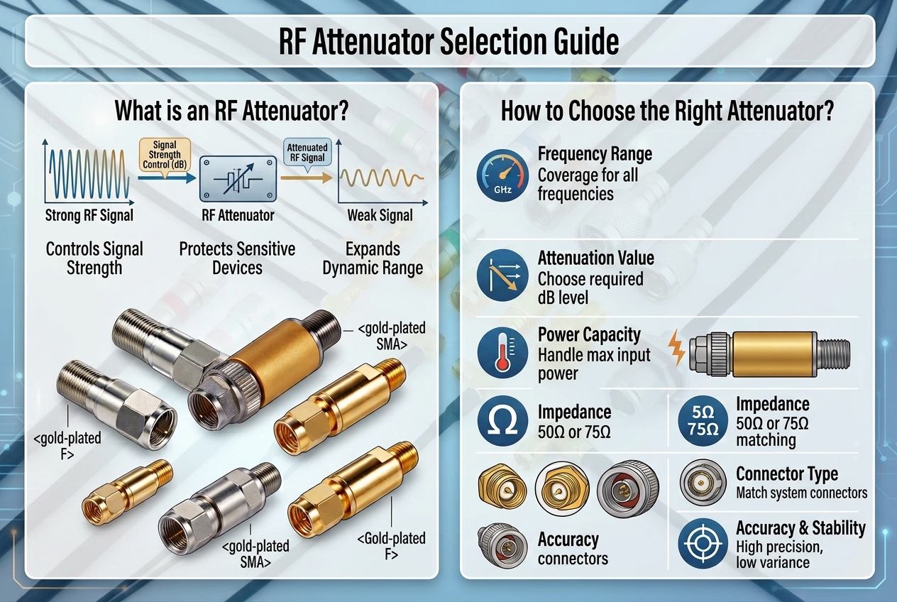
The selection of an RF attenuator depends on the specific system application, electrical requirements, and the trade-off between cost, accuracy, and power handling capability.
First, clarify the primary intent: whether it is needed to protect sensitive equipment, level signal strength, match system impedance, or extend instrument dynamic range.
Second, evaluate technical performance metrics. Key electrical specifications include Operating Frequency, Attenuation Value (dB), Power Rating (CW & Peak), Impedance, VSWR/Return Loss, and Connector Interfaces (e.g., SMA, N-type, BNC).
Finally, determine the type of attenuator (Fixed, Variable, or Digital/Programmable) and define the necessary testing protocols to ensure stable and reliable performance under actual operating conditions.
Q. What is the primary function of an RF attenuator?
Ans: An RF attenuator is a passive component designed to reduce the power (amplitude) of a radio frequency signal by a precise amount without noticeably distorting its waveform, phase, or frequency profile.
Q. Why would you use an attenuator in an RF system?
Ans: Attenuators are commonly deployed for four critical reasons:
• Protect Sensitive Equipment: Prevents high-power RF sources from overdriving or permanently damaging delicate test equipment (e.g., spectrum analyzers, oscilloscopes).
• Signal Level Control: Adjusts power levels between system components to keep signals within their linear operating range and prevent saturation.
• Improve Impedance Matching (VSWR Improvement): Placed between mismatched RF stages, an attenuator absorbs reflected power and reduces overall VSWR, stabilizing signal transmission.
• Extend Dynamic Range: Allows test systems to accept higher input power levels than their default hardware limits allow.
Q. What are the main disadvantages or trade-offs of using an attenuator?
Ans: While highly effective, using an attenuator introduces a few trade-offs:
• Power Dissipated as Heat: Reduced signal power is converted into thermal energy, which requires adequate power handling and heat dissipation in high-power applications.
• Signal-to-Noise Ratio (SNR) Reduction: Attenuation reduces signal strength relative to thermal noise, which can increase the overall system Noise Figure.
• Unintended Signal Loss: If placed improperly in a low-power receive path, it can push weak signals below readable receiver sensitivity levels.
Q. Which is the "best" RF attenuator for my application?
Ans: There is no single "best" attenuator—the optimal choice depends on your specific performance requirements and operational environment:
| Attenuator Type
|
Primary Advantage
|
Typical Applications
|
Fixed Coaxial Attenuator | High accuracy, flat frequency response, reliable | Test & measurement pads, fixed system level balancing |
Variable / Step Attenuator | Manual tuning in precise, calibrated steps | Lab prototyping, manual gain adjustment |
Digital / Voltage-Controlled | High-speed automated control via digital commands | AGC loops, phased array systems, automated test equipment (ATE) |
High-Power Attenuator | High heat dissipation (tens to hundreds of Watts) | Transmitter output testing, high-power RF loads |
Q. What key parameters should be confirmed before purchasing or customizing an RF attenuator?
Ans: You should systematically review the following parameters:
- Operating Frequency Range: Must cover or exceed your target band (e.g., DC to 6 GHz, DC to 18 GHz).
- Attenuation Value & Tolerance: Specify required dB reduction (e.g., 3 dB, 6 dB, 10 dB, 20 dB) and allowable tolerance.
Power Handling Capability: Confirm both continuous wave (CW) power and peak pulse power ratings exceed your maximum input level.
Impedance & Connector Types: Match your system’s characteristic impedance (typically 50 Ω or 75 Ω) and connector interfaces (SMA, N-type, BNC, 2.92mm, etc.).