


50 ohm
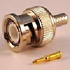
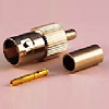
BNC1150-1-XXX
BNC STR. PLUG CRIMP TYPE
Suitable Cable:
(1)RG58
(2)RG174, RG188, RG316
(3)RD316
BNC STR. PLUG CRIMP TYPE
Suitable Cable:
(1)RG58
(2)RG174, RG188, RG316
(3)RD316
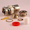
BNC1150-2-XXX
BNC STR. PLUG CLAMP TYPE
Suitable Cable:
(1)RG58
(2)RG8, RG213, RG393
BNC STR. PLUG CLAMP TYPE
Suitable Cable:
(1)RG58
(2)RG8, RG213, RG393
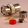
BNC1150-2-XXX
BNC STR. PLUG CLAMP TYPE
Suitable Cable:
(1)RG174, RG188, RG316
(2)RD316
BNC STR. PLUG CLAMP TYPE
Suitable Cable:
(1)RG174, RG188, RG316
(2)RD316
BNC1250-1-XXX
BNC R/A PLUG CRIMP TYPE
Suitable Cable:
(1)RG58
(2)RG174, RG188, RG316
(3)RD316
BNC R/A PLUG CRIMP TYPE
Suitable Cable:
(1)RG58
(2)RG174, RG188, RG316
(3)RD316
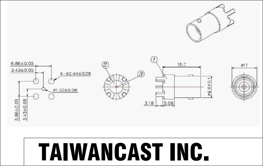
BNC6150-4
BNC STR. JACK P.C.B. MOUNT
BNC STR. JACK P.C.B. MOUNT
BNC6150-4
BNC STR. JACK P.C.B. MOUNT
BNC STR. JACK P.C.B. MOUNT
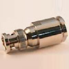
BNC6150-5
BNC STR. JACK BULKHEAD RECEPTACLE
BNC STR. JACK BULKHEAD RECEPTACLE

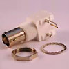
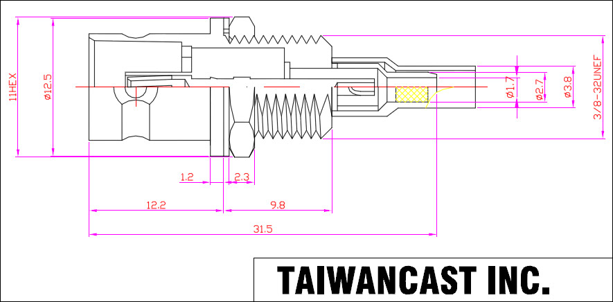
BNC8150-1-XXX
BNC STR. JACK BULKHEAD CRIMP TYPE
Suitable Cable:
(1)RG58
(2)RG174, RG188, RG316
(3)RD316
BNC STR. JACK BULKHEAD CRIMP TYPE
Suitable Cable:
(1)RG58
(2)RG174, RG188, RG316
(3)RD316
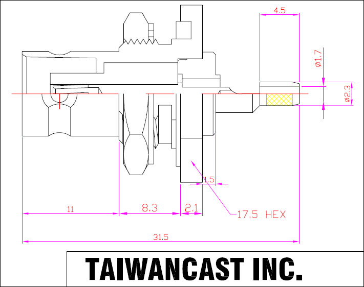
BNC8150-3-XXX
BNC STR. JACK BULKHEAD SOLDER TYPE
Suitable Semi-Rigid Cable:
(1) .085
(2) .141
BNC STR. JACK BULKHEAD SOLDER TYPE
Suitable Semi-Rigid Cable:
(1) .085
(2) .141
BNC8250-4
BNC R/A JACK BULKHEAD P.C.B. MOUNT
BNC R/A JACK BULKHEAD P.C.B. MOUNT
75 ohm
BNC1175-2-XXX
75 ohm BNC STR. PLUG CLAMP TYPE
Suitable Cable:
(1)RG59
(2)RG6
(3)RG11
75 ohm BNC STR. PLUG CLAMP TYPE
Suitable Cable:
(1)RG59
(2)RG6
(3)RG11
BNC6175-1-179
75 ohm BNC STR. JACK CRIMP TYPE
Suitable Cable:
(1)RG59
(2)RG179
75 ohm BNC STR. JACK CRIMP TYPE
Suitable Cable:
(1)RG59
(2)RG179
BNC8175-1-XXX
75 ohm BNC STR. JACK BULKHEAD
CRIMP TYPE
Suitable Cable:
(1)RG59
(2)RG179
75 ohm BNC STR. JACK BULKHEAD
CRIMP TYPE
Suitable Cable:
(1)RG59
(2)RG179
2F, No.27, Jhong-Rong St., Sin-Jhuang Dist., New Taipei City 24248, Taiwan
Tel :886-2-89941601 Fax :886-2-89941602
E-mail :sales@rfconnector.com.tw
Tel :886-2-89941601 Fax :886-2-89941602
E-mail :sales@rfconnector.com.tw
Copyright © TAIWANCAST INC. All Rights Reserved.